24VAC Common Wire Architecture for Ecobee and Honeywell Thermostats
Testing by National Equipment Parts Archive in 2026 confirms Wi-Fi thermostats draw 2.5 to 4.2 VA continuously, requiring 24VAC +/-10% under load.
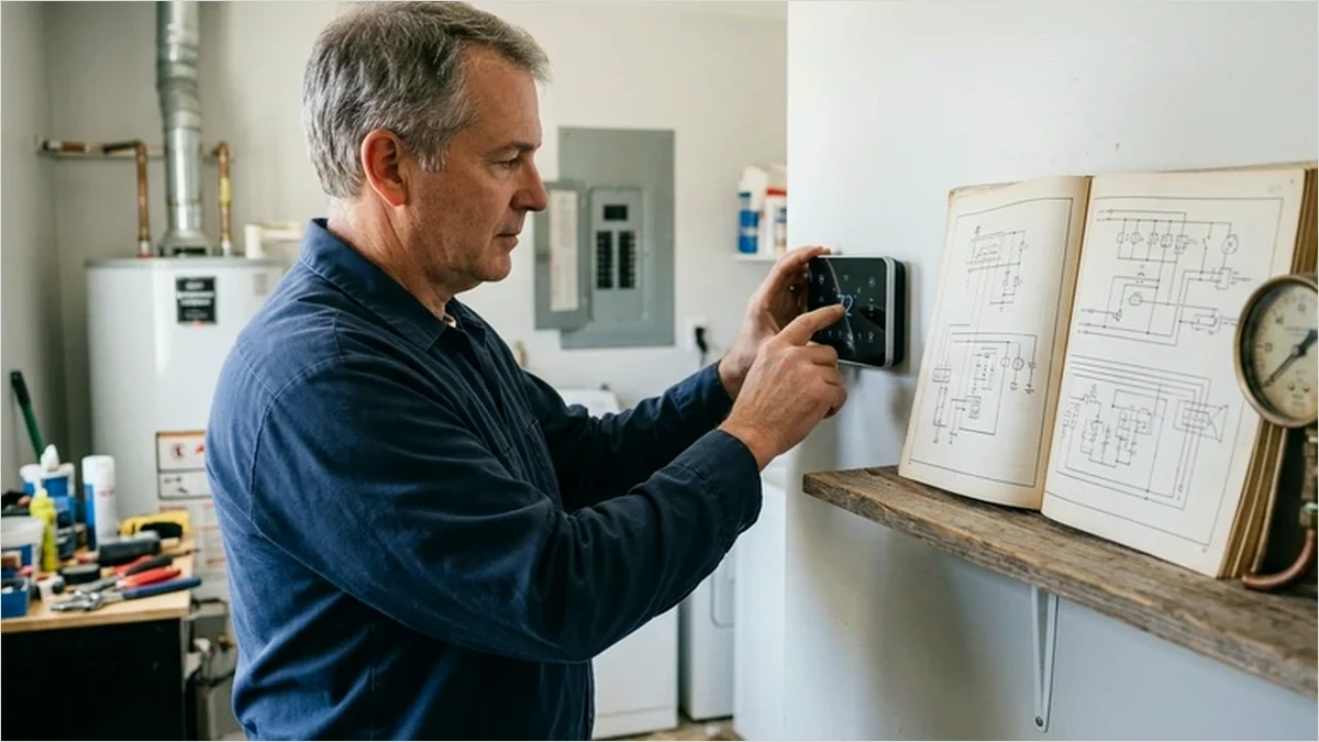
- Modern Wi-Fi thermostats consume 2.5 to 4.2 VA continuously on the R-to-C circuit, unlike mechanical mercury or battery-only stats.
- Standard 40 VA furnace control transformers leave roughly 15 to 20 VA of spare capacity after powering a gas valve and blower relay.
- Power-stealing thermostats without a dedicated C-wire can cause contactor chatter on older carrier and Trane air handlers.
- Ecobee PEK and Honeywell C-Wire adapters multiplex the Y and G signals only when at least 4 intact conductors reach the air handler.
Why 24VAC Control Circuits Need a Dedicated Return Path
Residential and light commercial HVAC control circuits standardize on Class 2 24VAC power stepped down from 120V or 240V line voltage through a control transformer. In legacy mechanical or battery-powered thermostats, the wall unit acted solely as a dry-contact switch: it bridged R (24VAC hot) to W (heating), Y (cooling), or G (fan) without drawing continuous current for itself. Smart controls such as the Ecobee SmartThermostat Premium and Honeywell Home T6 Pro Wi-Fi incorporate color capacitive touchscreens, dual-band Wi-Fi radios, and occupancy radar sensors that require uninterrupted DC power rectified from the 24VAC bus.
When a thermostat attempts to power its radio without a dedicated C (common) conductor, it must trickle current through the heating or cooling relay coil back to the transformer neutral. On modern variable-speed ECM control boards, this leakage current often triggers false call-for-heat faults, rapid relay chattering, or brownout reboots whenever the compressor contactor pulls in and briefly sags bus voltage below 19.5 VAC.
Transformer VA Budgets and Voltage Tolerance Benchmarks
Before installing a smart thermostat or adding accessories like an evaporative humidifier solenoid and fresh-air damper, technicians must sum the holding and inrush volt-ampere (VA) demand on the 24VAC transformer. A typical 40 VA factory transformer supports the furnace integrated control module, gas valve, and a single-stage condensing unit contactor, but adding multiple smart thermostats in a zoned damper panel frequently exceeds 40 VA and requires upgrading to a 75 VA Class 2 transformer.
| Control Component | Nominal Voltage | Steady-State Load (VA) | Inrush / Peak (VA) | Circuit Terminal |
|---|---|---|---|---|
| Ecobee SmartThermostat | 24 VAC (18-30V) | 3.5 VA | 4.8 VA | Rc / C |
| Honeywell T6 Pro Wi-Fi | 24 VAC (18-30V) | 2.8 VA | 4.0 VA | R / C |
| 24VAC Gas Valve (Single-Stage) | 24 VAC | 12.0 VA | 16.5 VA | W / C |
| AC Condenser Contactor Coil | 24 VAC | 7.5 VA | 14.0 VA | Y / C |
| Aprilaire Humidifier Solenoid | 24 VAC | 2.3 VA | 3.2 VA | HUM / C |
Multiplexing Adapters vs. Pulling 18/5 or 18/8 Thermostat Cable
When existing wall wiring contains only four conductors (R, W, Y, G) and pulling new 18/5 or 18/8 solid copper cable is structurally impractical, both Ecobee (Power Extender Kit) and Honeywell (C-Wire Power Adapter) offer active multiplexing modules mounted inside the air handler cabinet. These modules combine the Y and G control signals onto a single wire using a high-frequency carrier or diode-rectified signaling, freeing the fourth conductor to serve as a dedicated C-wire return. While effective on standard single-stage heat/cool systems, multiplexing adapters are incompatible with two-stage cooling (Y2), two-stage heating (W2), or proprietary communicating buses.
Field Commissioning Checks for 24VAC Control Loops
After terminating thermostat conductors at the furnace control board, verify steady-state and under-load voltages with a true-RMS multimeter before snapping the faceplate onto the wall subbase.
- Measure R to C with all loads idle: healthy transformers read between 25.0 VAC and 27.5 VAC open-circuit.
- Engage both W (heating) and Y (cooling test) or humidifier solenoid simultaneously; bus voltage must remain above 21.5 VAC.
- Inspect the low-voltage 3A or 5A ATC blade fuse on the furnace board and confirm no bare copper exceeds 1/4 inch at screw terminals.
- Confirm unused spare conductors in 18/8 bundles are neatly wrapped around the jacket rather than grounded to the chassis.
Nine out of ten intermittent Wi-Fi thermostat dropouts trace back to marginal 24VAC transformer sag under compressor inrush rather than wireless router interference. -- National Equipment Parts Archive Field Audit, 2026
Technical Frequently Asked Questions
What happens if R and C read 26 VAC open-circuit but drop to 17 VAC when the AC turns on?
A sharp voltage sag under load indicates an undersized 40 VA transformer, a high-resistance splice in the thermostat cable, or a failing condenser contactor coil drawing excessive inrush current.
Can I use a plug-in 24VAC wall transformer instead of running a C-wire to the furnace?
Yes, on cooling-only or heat-only setups that support separate Rc/Rh terminals, but you must follow the manufacturer wiring diagram carefully so two transformers are never tied together in parallel.
Why does Honeywell T-Series documentation specify 18-gauge solid copper wire?
18 AWG solid copper minimizes voltage drop over runs up to 150 feet and seats reliably in spring-clamp terminal blocks without fraying like stranded speaker wire.